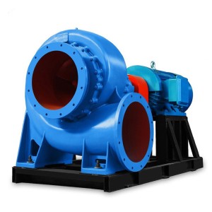
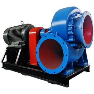
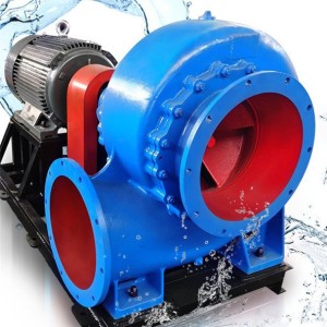
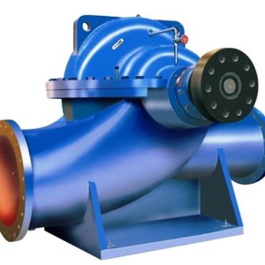
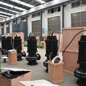
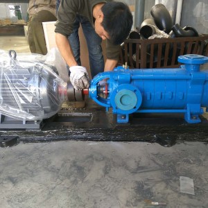
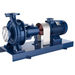
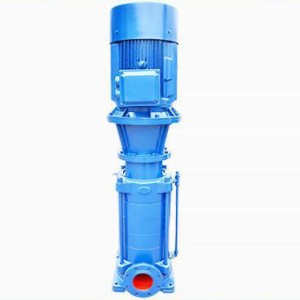
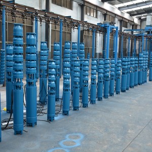
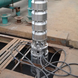
The installation height of the pipeline centrifugal pump is very critical during installation. The inlet pipeline of the pipeline centrifugal pump cannot be higher than the liquid level without the bottom valve installed, and must be lower than the inlet liquid level, that is, the liquid must be able to be poured into the pump body. It is only possible when the bottom valve is installed, and the suction stroke should be controlled within 6 meters.
The centrifugal force is the reason why the pipeline centrifugal pump can send water out. Before the pipeline centrifugal pump works, the pipeline centrifugal pump body and the water inlet pipe must be filled with water to form a vacuum state. When the impeller rotates quickly, the blades prompt the water to rotate quickly, and the rotating water flies away from the impeller under the action of centrifugal force. After the water in the centrifugal pump is thrown out, the central part of the impeller forms a vacuum area. The water from the water source is pressed into the water inlet pipe through the pipe network under the action of atmospheric pressure (or water pressure). In this way, continuous water pumping can be realized. It is worth mentioning here that the pipeline centrifugal pump must be filled with water in the pump casing before it can be started, otherwise the pipeline centrifugal pump body will not be able to complete liquid absorption, causing the pipeline centrifugal pump body to heat up, vibrate, and no water. “Idling” occurs, causing damage to the pipeline centrifugal pump (referred to as “air binding”) and causing equipment accidents.
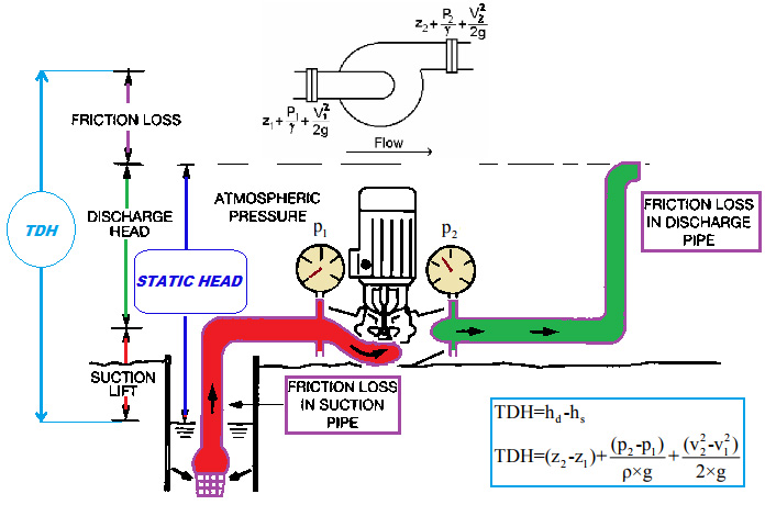
Calculation method of installation height of pipeline centrifugal pump
The allowable vacuum height Hs of the centrifugal pump refers to the maximum vacuum that can be reached by the pressure p1 at the inlet of the pump. The actual allowable suction vacuum height Hs value of the centrifugal pump is not the value calculated according to the formula, but the value measured by the pump manufacturer experimentally. This value is attached to the pump sample for users to check. It should be noted that the Hs value given in the pump sample is the value when clean water is used as the working medium, and the operating condition is 20℃ and the pressure is 1.013×10⁵Pa. When the operating conditions and working medium are different, conversion is required.
(1) Transporting clean water, but the operating conditions are different from the experimental conditions, can be converted according to the following formula: Hs1=Hs+(Ha-10.33)-(Hυ-0.24)
(2) Transporting other liquids. When the conditions of the liquid to be transported and the villain are different from the experimental conditions, a two-step conversion is required: the first step will be the Hs1 found in the pump sample according to the above formula; the second step will be the Hs1 according to the following formula Converted to H?s
2 NPSH Δh
For oil pumps, the cavitation allowance Δh is used to calculate the installation height, that is, the vacuum degree of the pump allowed to suck liquid, that is, the allowable installation height of the pump, in meters. Use the NPSH Δh to check from the oil pump sample, and its value is also measured with 20℃ clean water. If other liquids are to be transported, calibration is also required, and the relevant books should be checked in detail.
Suction range = standard atmospheric pressure (10.33 meters)-cavitation margin-safety amount (0.5 meters)
The vacuum height of the standard atmospheric pressure energy pressure pipeline is 10.33 meters.
For example: a certain pump must have a NPSH of 4.0 meters, what is the suction stroke Δh?
Solution: Δh=10.33-4.0-0.5=5.83 meters
From a safety point of view, the actual installation height of the pump should be less than the calculated value. When the calculated Hg is negative, it means that the suction port of the pump should be below the liquid level of the storage tank.
For example, a centrifugal pump found from the sample that the allowable vacuum height Hs=5.7m. It is known that the total resistance of the suction pipeline is 1.5mH2O, the local atmospheric pressure is 9.81×10⁴Pa, and the dynamic pressure head of the liquid in the suction pipeline is negligible. Try to calculate:
(1) Installation of the pump when delivering 20℃ clean water; (2) Changing the installation height of the pump when delivering 80℃ water.
Solution: (1) The installation height of the pump is known when delivering 20℃ clean water: Hs=5.7m Hf0-1=1.5m u12/2g≈0
The local atmospheric pressure is 9.81×10⁴Pa, which is basically in line with the experimental conditions when the pump leaves the factory, so the installation height of the pump is Hg=5.7-0-1.5=4.2m.
(2) The installation height of the pump when delivering 80℃ water
When delivering 80°C water, the Hs value in the pump sample cannot be directly used to calculate the installation height. The Hs time must be converted according to the following formula, that is, Hs1 = Hs + (Ha-10.33)-(Hυ-0.24)
It is known that Ha=9.81×10⁴Pa≈10mH2O, and the saturated vapor pressure of water at 80℃ is found to be 47.4kPa from the appendix.
Hv=47.4×10³Pa=4.83mH2O Hs1=5.7+10-10.33-4.83+0.24=0.78m
Substitute the value of Hs1 into the formula to obtain the installation height Hg=Hs1-Hf0-1=0.78-1.5=-0.72m
Hg is a negative value, which means that the pump should be installed below the liquid level of the pool, at least 0.72m lower than the liquid level.
How to install a pipeline centrifugal pump
The key to the installation technology of the pipeline centrifugal pump is to determine the installation height of the pipeline centrifugal pump (that is, the suction lift). This height refers to the vertical distance from the water surface of the water source to the center line of the pump impeller. It should not be confused with the allowable vacuum height. The allowable vacuum height indicated on the pump product manual or nameplate refers to the vacuum value on the section of the water inlet of the pump, and It is measured under 1 standard atmosphere pressure and water temperature of 20 degrees Celsius. It does not consider the water flow after the suction pipe is installed. The installation height of the water pump should be the value of the remaining part of the value after the vacuum height is allowed to suck up and the loss of the suction pipe is deducted. It must overcome the actual topographic water absorption height. The installation height of the pump should not exceed the calculated value, otherwise, the pump will not be able to pump water. In addition, the magnitude that affects the calculated value is the resistance loss head of the suction pipe. Therefore, it is advisable to adopt the shortest pipeline layout and install as few fittings as elbows. It is also possible to consider appropriately matching larger diameter water pipes to reduce the flow velocity in the pipe.
Post time: 2021-11-30


