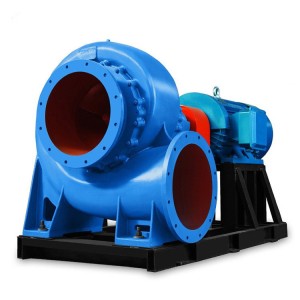
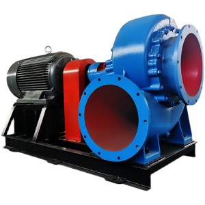
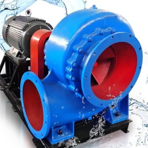
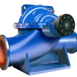
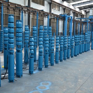
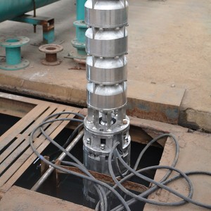
Type of pump
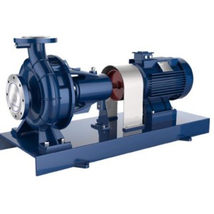
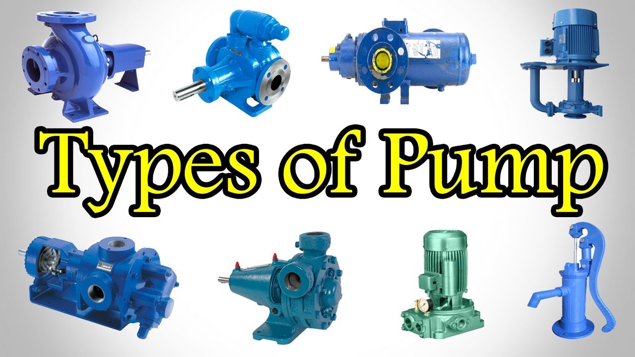
① The working principle of the centrifugal pump is: use the impeller blades to do work on the fluid, so that the pressure and kinetic energy of the fluid after passing through the impeller are increased, so the fluid can be transported to high places and far. Rotating, a vacuum is continuously formed at the entrance of the impeller, so that the fluid is continuously sucked and discharged by the impeller. Figure 1-1 is a simple structure diagram of the centrifugal pump. The centrifugal pump has the characteristics of large flow and high pressure head, and is widely used in power stations The speed of the centrifugal pump is generally very high.
② The working principle of the axial flow pump is to use lift to do work on the fluid to increase its pressure and kinetic energy. Its structure is shown in Figure 1-2. When the impeller rotates, the fluid flows in axially, and energy is obtained in the blade channel. Then, it flows out axially through the deflector. The axial flow pump is suitable for large flow and low pressure head, and is used as a circulating pump in a power station.
③ Reciprocating pumps have pistons and diaphragm pumps. They all rely on the reciprocating movement of pistons and pull rods in the pump cylinder liner to suck and discharge liquid. Pistons and pull rods constantly reciprocate, and the water absorption and pressure process of the pump is continuous Alternate operation. This type of pump is suitable for small flow, high pressure head, and the diaphragm has good sealing and anti-corrosion functions, so it is often used as a dosing pump and acid-base pump in power stations. Figure 1-3, Figure 1-4 Shown as a schematic diagram of a membrane pump and a reciprocating pump. For example, the SIR dosing pump of the Daya Bay Nuclear Power Station and the acid-base pump of YA are all diaphragm pumps.
④ The gear pump has a pair of mutually meshing gears, which are divided into a driving wheel fixed on the driving shaft and driven by the prime mover and a driven wheel mounted on the other shaft. When the gear rotates, the liquid enters the suction space along the suction pipe, along the upper and lower shell walls The two gears are respectively squeezed into the discharge space to join, and then enter the extrusion tube to discharge. The gear pump has stable working performance. It has good self-priming and is easy to transport viscous liquids, so it is often used as a lubricating oil pump. For example, CRF pumps The main lubricating oil pump is a gear pump.
2. Cavitation of water pump:
①The generation of water pump cavitation: due to various reasons, the pressure at the inlet of the water pump is lower than the saturation pressure of the working water temperature, which causes a part of the liquid to evaporate (that is, vaporization). When the vaporization occurs, there will be a lot of steam and gas dissolved in the water It escapes, forming a large amount of small vapor bubbles mixed with steam and gas. When the vapor bubble enters the high pressure area from the low pressure area, the vapor bubble rapidly condenses and ruptures under the action of high pressure. At the moment when the vapor bubble ruptures, the water becomes extremely high. The velocity flows to the space occupied by the original bubble, forming a strong impact force. This continuous local impact load will gradually fatigue the surface of the material and cause the erosion of the metal surface, thereby forming large and small honeycomb corrosion holes. In addition, by The oxygen that escapes from the liquid, with the help of the heat released when the vapor bubble is condensed, chemically corrodes the metal. The entire process of the formation, development and rupture of the vapor bubble and the destruction of the material is called cavitation.
② Consequences of cavitation
-Material damage: When cavitation occurs, the material is damaged due to the dual effects of mechanical erosion and chemical corrosion. Figure 2-1 shows a centrifugal pump impeller damaged by cavitation.
-Noise and vibration: due to the rupture of the vapor bubble, the high-speed rushing out caused serious noise. The sound caused by the cavitation of the water pump is generally a crackling popping sound. Furthermore, the cavitation process itself is a kind of repeated rushing out, The process of coagulation is accompanied by a large pulsating force. If a certain frequency of these pulsating forces is equal to the equipment’s own frequency, it will cause the pump to vibrate strongly.
-Decrease in efficiency: When cavitation is severe, the flow area is blocked due to the existence of a large number of bubbles, resulting in a drop in head and a decrease in flow rate.
③ Prevention and avoidance of cavitation
— Minimize the height of the water pump to increase the static pressure head at the inlet of the water pump.
— Adopt double suction impeller.
-Appropriately reduce the speed of the pump (e.g. booster pump for APP and APA pumps).
-Use impellers made of special materials (e.g. stainless steel impellers).
3. Generation and balance of axial thrust
① Generation of axial thrust: When the single-suction pump is running, because the pressure acting on both sides of the impeller is not equal, an axial thrust that points to the suction port of the pump and is parallel to the shaft is generated. The downward force caused by the weight of the one-axis pump is added. The value of the axial thrust is large, which will press the entire rotor against the suction port, which is very harmful to the normal operation of the pump.
② Balance of axial thrust:
— Double-suction impeller (only for single-stage pumps). The double-suction impeller does not produce axial force in theory due to the symmetrical structure of the left and right. However, due to manufacturing errors, the degree of wear and leakage of the seal rings on both sides is different, Will produce residual axial thrust. In order to balance this part of the remaining axial thrust, thrust bearings are mostly used at the same time. For example, APP’s booster pump and pressure pump are single-stage double-suction impellers, which are installed at the non-driving end of the two pumps at the same time There are two-way thrust bearings. Figure 3-1.
— Multi-stage pumps can be arranged symmetrically:
If the number of stages of the multi-stage pump is even, it can be back-to-back or face-to-face in series on a shaft, but this method cannot completely balance the axial force, and a thrust bearing must be installed to withstand the remaining axial force. .Figure 3-2.
— Balance plate, balance hole and thrust bearing:
At present, some large and small pumps only use thrust bearings to balance the axial thrust. For example, the CRF circulating water pump of our factory relies on a one-way thrust bearing to balance the axial thrust.
4. Shaft end seal of water pump
The pump shaft passes through the pump casing, so there is a gap between the moving and static parts, and the liquid in the pump will leak out of the pump. If the leaked liquid is toxic and corrosive, it will pollute the environment; if the suction port is vacuum, it will cause Air leaks into the pump, which seriously threatens the normal operation of the pump. In order to reduce leakage, shaft end sealing devices are generally installed at the gap between the static and dynamic parts. There are two commonly used packing seals and mechanical seals.
① Packing seal:
The seal is achieved by contact between the packing and the surface of the shaft (or shaft sleeve). The tightness of the shaft seal can be adjusted by the method of tightening the packing. The packing seal requires a small amount of leakage during operation. Therefore, it cannot be used for toxic and corrosive liquids. This kind of sealing method is adopted. The packing ring used in conjunction with the packing seal introduces the sealing water with higher pressure to the surface of the shaft for lubrication and cooling; if the pressure at the shaft passing through the pump is less than the atmospheric pressure outside the pump, there is a gas barrier Function. Figure 4-1 is a schematic diagram of packing seal.
② Mechanical seal:
The main components are the moving ring (rotating ring) and the static ring (fixed ring). During operation, the moving ring and the static ring are tightly attached to each other for relative movement, so as to prevent leakage and seal (the moving ring can be moved along Axial movement). When the mechanical seal is working, the surface of the moving ring and the static ring continue to rub and heat. If it is not well cooled and flushed, the mechanical seal will be damaged. Therefore, the mechanical seal cooling, Flushing water. At the same time, it also has the function of preventing air from entering the pump. The shaft end of the main water pump of the Daya Bay Nuclear Power Plant is sealed due to the particularity of the fluid (such as sea water, boron or radioactivity, etc.) or the pump speed is high (APP, APA pump) Most of them use mechanical seals. In addition, due to the nature of the fluid in the pump, temperature and other reasons, the source of the sealing water is not the same. During normal operation, the sealing water of the APP, APA, and CEX pumps comes from the outlet distribution pipe of the CEX pump; The sealing water of the CRF pump from SDA, SRI and RRI pumps is supplied by the high pressure end of the pump itself.
5. The operation of the water pump
① Inspection before starting the water pump:
-Before starting the pump, check the power supply equipment first, ask the electrician to measure the insulation resistance of the motor, and then send it to the power supply.
-Check that the bearing lubricating oil level is normal (usually 2/3 of the oil level gauge). For water pumps that use circulating oil lubrication, confirm that the oil pump has been started and operating normally, and observe the oil return through the oil return window.
-Manually crank the pump shaft (small pump) or put into operation an electric crank (large pump, such as APP pump), check whether there is friction and knocking noise in the pump.
-Check that the water supply valve of the motor cooler is open and the flow is normal.
— For cold-started APP and APA pumps, heat pumps must be used.
-Check the compression of the stuffing box stuffing, the stuffing sealing water, mechanical sealing water, cooling water jacket cooling water, closed-loop mechanical sealing water cooling water has been sent, and the flow rate is normal.
-Check that all water and oil side instrument valves of the pump are open, the thermometer is in place, the electrical instruments are put into operation, and the indications of all instruments are correct.
-Check that the power supply of the electric valve, the operation power supply, and the compressed air of the pneumatic valve have been sent.
-Check that the water level of the water source is normal, and the outlet valve of the water pump is closed (for axial flow pump gears, it should be opened).
— Open the inlet valve and exhaust valve of the water pump to fill and exhaust. After the water pump exhaust valve discharges normally, close the exhaust valve.
② After the water pump is started:
-During the startup of the water pump, pay attention to whether there is smoke in the motor terminal box, and whether there is abnormal noise and vibration.
— For newly installed water pumps or water pumps whose motors have been overhauled, it is necessary to check whether the direction of rotation of the motor is correct.
-Check the motor bearing temperature and whether the vibration is normal.
-Check whether the motor current and the inlet and outlet pressure of the water pump are normal or not.
— Check the temperature rise rate of each bearing of the water pump. If the temperature rises quickly, stop the pump to find the cause.
— Check the shaft end seal. The leakage of the packing seal is generally 10-30 drops per minute. In addition, the first time the pump is started after the maintenance, check whether the seal is smoking or hot. If it is serious, loosen the sealing gland screw Wait.
-Check the water pump pipeline, especially the connecting parts of the high-pressure end pipeline for leaks.
③ Inspection items during normal operation of the pump:
— Regularly observe whether there is an alarm signal on the control panel, and reset it immediately. If the fault is true, report it immediately and fill in the “job application”.
— Regularly check and record the inlet and outlet pressure of the pump, motor current, bearing temperature, etc.
— During the inspection process, pay attention to listening to the internal sound of the water pump (the main parts include the bearing, the pump chamber, the packing seal and the mechanical seal), whether there is friction and collision sound. Of course, only the normal environmental noise and vibration during the operation of the water pump are enough Only by understanding and understanding can we have a keen resolution to abnormal noise and vibration.
— Frequently check the lubrication of the bearing. Regardless of whether there is a temperature meter, under the premise of each piece of permission and ensuring personal safety, use your hands to touch the bearing to feel the change in bearing temperature. For large pumps that circulate oil, Check the working conditions of the oil supply system equipment (oil pump, oil tank, oil cooler, filter, oil purifier, etc.): observe whether the oil return is unblocked and the oil quality is good through the oil return window.
6. Isolation of the water pump and water filling and exhaust
① Isolation of water pump
-After confirming that the pump is out of service, disconnect its power supply and operating power on the power supply panel.
-Close the inlet and outlet valves of the pump and the recirculation valve.
— When the fluid in the pump needs to be drained, first open the downstream valve of the drain funnel. When opening the small valve, remember to do it slowly. After opening a little to relieve the pressure, then gradually open it according to the downstream drainage capacity. Especially when the fluid in the pump is high temperature, high pressure, corrosive or radioactive, you must be more careful to avoid physical injury and environmental pollution.
— During the drainage process, closely monitor whether the relevant system is operating normally, whether there is pressure, drop in liquid level, and abnormal opening of the water supply valve at a regular time. If the above situation occurs, the drainage should be immediately suspended and the cause should be quickly identified.
— Only when there is no more water flowing out of the drain pipe, and the related systems are operating normally, they can leave.
② Filling and exhausting the water pump:
— Check that the inlet and outlet valves and traps of the water pump are in the closed position;
-Open a few inlet valves, and gradually open the exhaust valve (note that liquid splashing can cause harm to the body), after the exhaust pipe has evenly discharged water and no gas escapes, close the exhaust valve and fully open the inlet valve.
-When filling and exhausting a closed-cycle large-capacity water pump, slowly control the speed of filling and exhausting to prevent disturbance to the system.
7. Operating characteristics of special pumps: gear pumps and diaphragm pumps
① Gear pump: The gear pump has stable working performance and good self-priming. It is often used as a lubricating oil pump in power stations, such as the CRF main oil pump of our factory. The gear oil pump runs uniformly and has low pressure fluctuations. The pressure of the gear pump The control is achieved by a safety valve on the outlet pipeline. When the outlet pressure of the gear pump exceeds the safety valve action threshold, the safety valve operates to make a part of the high-pressure oil return to the inlet end.
② Diaphragm pump: Since the membrane of the diaphragm pump is embedded in the cylinder liner, it prevents the leakage of liquid and the corrosion of the mechanical parts. Therefore, it is often used as a dosing pump in power stations, such as the SIR dosing pump is a diaphragm pump The diaphragm pump sucks and discharges liquid by the alternate operation of the piston rod pulling and pushing the membrane. During operation, the pressure fluctuates greatly and the flow is unstable. Generally, an absorber is installed on the outlet pipe section to balance the pulsation caused by the positive displacement pump. It is the same as the gear pump. The pressure is also controlled by the safety valve. In addition, the diaphragm pump can adjust the flow rate by adjusting the piston stroke as needed.
Post time: 2021-12-07


