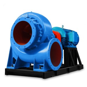
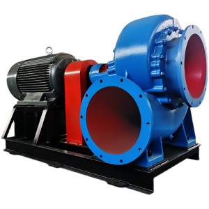
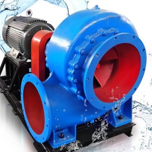
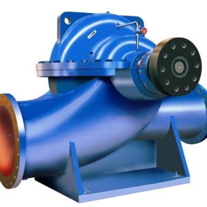
1. Introduction to the pump
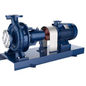
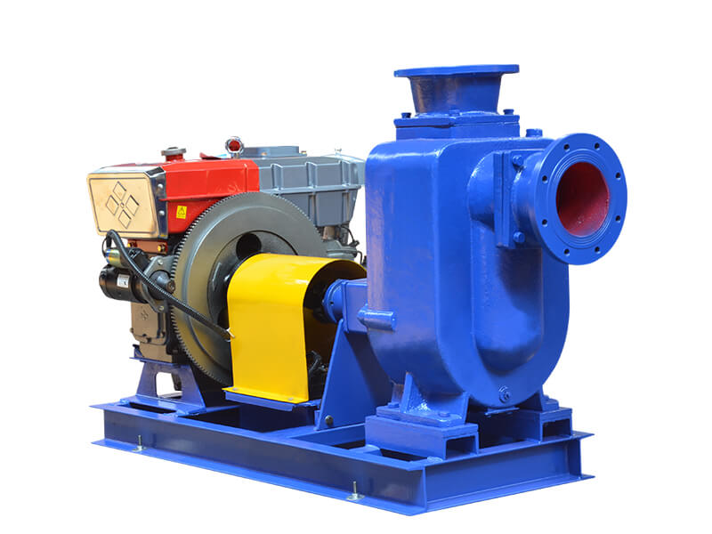
ZX series are horizontal, single-stage single-suction cantilever centrifugal pumps. The temperature of the working medium ranges from -80°C to +350°C, the working pressure can reach 1.6Mpa, and the head is 5 to 125m.
2. Working principle and structure description
The pump adopts axial liquid return pump body structure. The pump body is composed of a suction chamber, a liquid storage chamber, a scroll chamber, a liquid return hole, a gas-liquid separation chamber, etc. After the pump is started normally, the impeller will suck the liquid stored in the suction chamber and the air in the suction pipe together, and It can be completely mixed in the impeller. Under the action of centrifugal force, the liquid entrains the gas and flows to the outer edge of the scroll. A certain thickness of white foam belt and high-speed rotating liquid ring are formed on the outer edge of the impeller. The gas-liquid mixture enters the gas-liquid separation chamber through the diffuser. At this time, due to the sudden decrease of the flow rate, the lighter gas is separated from the mixed gas-liquid, and the gas continues to rise and be discharged through the outlet of the pump body. The degassed liquid returns to the liquid storage chamber, and enters the impeller again through the return hole, mixes with the gas sucked from the suction pipe inside the impeller, and flows to the outer edge of the impeller under the action of the high-speed rotating impeller. As this process goes on again and again, the air in the suction pipeline is continuously reduced until the gas is exhausted and the self-priming process is completed, and the pump is put into normal operation.
3. Matters needing attention when starting and stopping:
(1) Preparation and inspection before starting:
1. Check the lubricating oil level. If the oil level is insufficient, add lubricating oil.
2. Check whether the liquid storage in the pump casing is higher than the upper edge of the impeller. If it is insufficient, you can directly inject the liquid storage into the pump body from the liquid filling port on the pump casing. It should not be started when the liquid storage is insufficient. , Otherwise the pump will not work normally and the mechanical seal will be easily damaged.
3. Check whether the rotating parts of the pump are stuck or bumped.
4. Check whether the nuts of the pump body and the joints are loose.
5. Check the coaxiality and parallelism of the pump shaft and the motor main shaft.
6. Check whether the inlet pipeline is leaking. If there is any leak, try to eliminate it.
7. Open the valve of the suction pipeline.
(2) Matters needing attention during pump operation:
1. You can start the pump formally, slowly open the outlet valve to observe whether the flow and pressure meet the requirements;
2. Pay attention to monitoring the inlet liquid level;
3. Observe the overall operation of the pump including:
a. Whether the packing and mechanical seal are leaking
b. The temperature rise of the bearing temperature cannot exceed 40 degrees, and the maximum temperature cannot reach 75 degrees;
c. The vibration of the pump body and pipeline; whether the pump has noise and whether the pump current meets the requirements.
4. Daily maintenance
a. Regularly check the smoothness of pump operation every day, whether there is vibration, pay attention to changes in operating noise, changes in bearing temperature, whether there is leakage in the seal, and whether there is any change in the lubricating oil level;
b. Check the pressure, flow and temperature of the pump inlet and outlet regularly every day and make a record;
c. Motor operating parameters, and record;
d. For the initial operation of the bearing for 10-15 hours, new lubricating oil should be replaced;
(3) Starting and operation:
1. Start the self-priming pump and pay attention to whether the direction of the pump shaft is correct.
2. Pay attention to whether there are abnormal sounds and vibrations when rotating.
3. Pay attention to the readings of the pressure gauge and vacuum gauge. After starting, when the readings of the pressure gauge and vacuum gauge fluctuate for a period of time and the indication is stable, it indicates that the pump has been filled with liquid and enters the normal infusion operation.
4. Before the pump enters the normal infusion operation, that is, during the self-priming process, special attention should be paid to the rise of the water temperature in the pump. If the process is too long and the water temperature in the pump is too high, stop the pump to check the cause.
5. If the temperature of the liquid in the pump is too high to cause difficulty in self-priming, you can temporarily stop it, and use the liquid in the output pipeline to flow back into the pump or directly replenish the liquid into the pump at the liquid-adding and storage port on the pump body. Cool the liquid in the pump and start it.
6. If the pump has strong vibration and noise during the working process, it may be caused by the cavitation of the pump. There are two reasons for the cavitation: one is that the flow velocity of the inlet pipe is too large, and the other is that the suction lift is too high. When the flow rate is too high, the outlet control valve can be adjusted to increase the pressure gauge reading. When the inlet pipeline is blocked, it should be eliminated in time; when the suction lift is too high, the installation height of the pump can be appropriately reduced.
7. The outlet control valve should be slightly opened (not fully closed) when the pump is stopped for some reason during the working process and needs to be restarted. This is not only conducive to the discharge of gas from the outlet during the self-priming process, but also ensures that the pump is lighter. Start under the load.
8. Pay attention to check whether there is any leakage in the pipeline system.
(4) Stop the pump:
1. First, the valve on the outlet pipeline must be closed.
2. Stop the pump.
3. In the cold season, the liquid storage in the pump body and the water in the cooling chamber of the bearing body should be emptied to prevent freezing and cracking of the parts.
4, lubrication system
(1) Function: Reduce friction, reduce wear, and increase service life. Poor lubrication can cause serious consequences.
(2) System composition: oil tank, oil seal, sight glass, oil cup, exhaust hole, oil drain hole.
(3) Main points of maintenance:
a. Familiar with the lubrication system of the equipment in the area and the oil used.
b. Daily inspections to check the oil level of the equipment for leaks.
5, Replacement steps and methods of lubricating oil:
a. Shutdown;
b. Place a tray under the lubricating oil discharge hole to receive the oil;
c. Remove the screw plug, drain the lubricating oil completely, and screw on the screw plug;
d. Tilt the constant oil cup backwards and fill the bearing box with oil through the oil filling hole on the bearing box until the branch pipe of the constant oil cup starts to fill with oil. Pour the same kind of oil into the constant oil cup, and buckle the full oil cup again. Repeat the above process until there is at least 2/3 of the oil volume in the constant oil cup. Check the oil supply of the oil cup frequently and replenish it in time.
(5) Oil leakage treatment: follow the principle of plugging, sealing, leading, connecting, repairing, welding, changing, and changing. If it can be blocked, it will be blocked. If it cannot be blocked, it will be led back with a pipe. If you can’t go back, use the baffle or box to connect, repair the damaged parts, valves, and pipes, and replace them if they can’t be repaired. Weld the leaking seams and reform the design and manufacturing defects.
6. Maintenance of main parts
1. Overhaul of bearings
If the pump is running, if there is vibration, first disassemble it to check the wear of the bearing and the change of the geometric shape. Generally, the following should be overhauled.
1) The roundness of the bearing should not be greater than one thousandth of the shaft diameter. If it exceeds the standard, it should be replaced.
2) The surface roughness of the shaft diameter should meet the requirements.
3) Use Hongdan to grind the contact area between the shaft diameter and the bearing not less than 60% to 90%, and there should be no radial or axial scratches on the surface.
4) The inner and outer rings of the bearing should not tilt and derail, and should run flexibly.
5) The outer diameter of the ball bearing cannot contact the inner wall of the bearing housing.
6) The contact of the outer ring of the rolling bearing with radial load and the inner wall of the bearing box should adopt H/h coordination.
7) For the fit of thrust rolling bearing that does not bear radial load and shaft, the shaft adopts k6
Shaft diameter/mm gap/μm
18~30+7~-30
30~50+8~-35
50~80+10~-40
80~120+12~-41
120~180+14~-54
8) The housing and the bearing should be in close contact.
2. Overhaul of coupling
Couplings mainly include rigid couplings and toothed couplings.
1) Rigid coupling
Rigid couplings are generally used on centrifugal pumps with low power. First, remove the connecting bolts and rubber elastic ring during maintenance. For liquids with low temperature, the plane clearance of the two couplings is 2.2-4.2mm, and the temperature is relatively high. Should be greater than 1.55 ~ 2.05mm of the front channeling amount. The rubber elastic ring of the coupling should be 0.15~0.35mm smaller than the diameter of the perforation. At the same time, special tools must be used when disassembling and assembling, keep it clean and not allow bruises and scratches.
2) Gear coupling
The gear coupling has good flexibility and has automatic centering performance. The maintenance is generally carried out according to the following methods.
(1) Check the gear tooth surface meshing of the coupling. The contact area along the tooth height is not less than 50%, and the tooth width is not less than 70%. There should be no serious pitting, wear and cracks on the tooth surface.
(2) The full circle runout of the outer gear ring of the coupling is not more than 0.03mm, and the end circle runout is not more than 0.02mm.
(3) If it is necessary to remove the gear ring, special tools must be used, and no beating is allowed to avoid bending or damage to the shaft. When reinstalling, heat the ring gear to about 200°C before installing it on the shaft. The interference between the outer gear ring and the shaft is generally 0.01~0.03mm.
(4) When reinstalling the intermediate tube or other parts, it should be assembled according to the original markings and data.
(5) Tighten the bolts evenly with a torque lifter.
3. Maintenance of mechanical seal
When overhauling the mechanical seal, first use special tools to correctly remove the dynamic and static rings of the mechanical seal, and check the wear of the end face. For the rotor of the pump with the mechanical seal, dynamic or static balance tests should be performed regardless of the power. In order to ensure that the sealing surface does not leak, the dynamic and static surfaces can be pressed tightly on the fitter’s platform, and water is poured for a leakage test. If the static water does not leak, the surface roughness and flatness of the sealing surface meet the requirements. The verticality deviation of the end face during installation is not more than 0.015mm.
7, safety precautions
1. The pump should be completely handed over, powered off, and listed before any overhaul.
2. Strictly abide by the overhaul regulations and relevant company and national safety regulations.
Post time: 2021-12-07


